
Garlon Fulton dubbed the time following the rigid airship losses “the years of confusion,” but American airship interests were not sitting still as the Zeppelin men recovered from the fire and perfected the LZ-130. As we see in a section of Popular Science, April 1938, “Can the Zeppelin Come Back?” By Edwin Teale: “While the Germans are preparing new sky liners for use on the 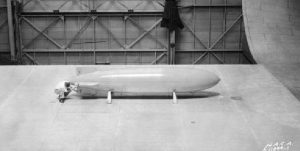 long-distance Airways of the world, American scientists are busy with scale models, imitation landing fields, swirling water, and trailing smoke. Another series of tests has been carried out at the great National Advisory Committee for Aeronautics wind tunnel at Langley Field, Virginia. Here, [photo, left] a 20 foot model of the Macon, the U.S. Navy’s ill-fated zeppelin, was constructed of wood and finished so that the exterior reproduced the same type of surface as well – doped fabric… While smoke streamed down the model, a 16mm moving – picture camera recorded the way it swirled around the nose of the model when it was placed at different angles in the slipstream. Almost every condition and airship meets in coming to ground and while being maneuvered about by a landing crew, can be reproduced in miniature by this method. Rolling, pitching, yawing, as well as meeting headwinds, tailwinds, and crosswinds, have been investigated by the men at Langley Field.”
C. E. Rosendahl, in his book SNAFU, discussed much more elaborate testing at the time: “The loss of the MACON precipitated a decision to engage in a thorough fundamental research program for reappraising all airship aerodynamic requirements. Fostered by members of the Durand Committee, the Bureau of Aeronautics made a special research grant to the Guggenheim Airship Institute resulting in ingenious techniques and new forms of model testing.”
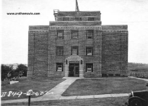 Photo Courtesy Ed Fielding, USS Akron/Macon riveter: A view of the Daniel Guggenheim Airship Institute in Akron shortly after its completion. (The building still stands.) Rosendahl continued, “One of these was the attachment of an airship model to a whirling arm whereby precision measurements can be made of the stresses brought on the model in motion, both with and without gust effects. …”
Popular Science described in great detail its elaborate central feature: “Using a water tank instead of a wind tunnel, aeronautical experts at the Daniel Guggenheim Airship Institute are testing a curious ‘underwater dirigible…’ They are obtaining, in the laboratory, new information about the Zeppelin and its problems… The scientists at Akron are accumulating facts of value to designers and navigators alike… “
 “Machined from magnesium, the model is 5 feet long and about 10 inches in diameter. It is so designed that it can be ballasted with water until it weighs exactly the same as the fluid it is displacing. In this condition, it reacts to eddies and currents of water just as an airship, riding on even keel in the sky, reacts to winds and gusts of air,” explained the Popular Science article. Goodyear’s own diagram, shown here, illustrates the testing in a water tank concept. The 1/150th scale model fit well into the 8 foot wide, 23-foot long channel as i tiny electric motors simulated real engines.
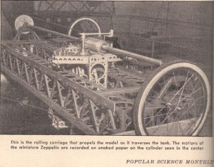
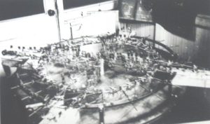
Popular Science continued, 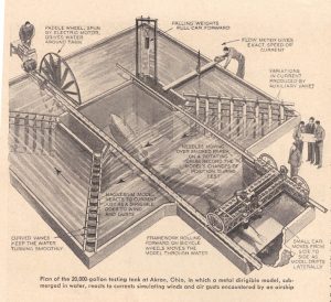 “At one side of the 20,000 – gallon tank, there is an eight – foot paddle wheel, formed of 16 slim propeller blades. Spun by a direct – current electric motor, it drives the water in a clockwise direction around the 34 -foot tank. Curved fins at the corners keep the liquid flowing smoothly, instead of piling up and swirling around at the turns… Imagine yourself witnessing one of the Akron tests. You descend to the basement of the laboratory at the municipal airport, where the scientists are busily adjusting the model, ballast in yet so that it has no weight in the water… Lowered into the tank, and it is attached to a vertical member carried by a small car which is free to roll on a framework of girders. This framework, in turn, is mounted on three bicycle wheels so it moves forward at right angles to the motion of the small car, pulled by a falling weight. Smoked paper is affixed to a recording drum at the top of the vertical member into needles are set at the zero position… One line indicates the lateral movements, the other the twisting of the model.”
 The Popular Science illustration (right) shows girders similar to Akron-Macon’s strongest used in construction of the test arm. “The relative speeds of water and model represent, when magnified to zeppelin’s proportions, strain – producing conditions such as are met in high winds and gusty weather. The accumulating record sheets provide a basis for later calculations which will reveal much about the forces which act on an airship in flight and on the ground…”
 The testing yielded reams of data that would greatly enhance understanding of loads experienced but a rigid airship hull. Goodyear’s own summary, probably intended for in-house use and probably too complicated for general publication, reveals a great deal about design trends and piece-part tests at that time.
 Rosendahl specified, “There were also testing machines by which full-scale girders or other members could be tested and tortured at varying loads up to their final destruction points.” Motion pictures used in Rosendahl’s postwar rigid airship history film, included in our DVD The Flying Carriers, show Goodyear-Zeppelin’s Dr. Karl Arnstien handling this newly designed girder. Shown here in the test rig, the girder resembles a design more in keeping with the contemporary German practice. The film also shows this girder being load-tested on that machine. While the study does not specifically mention the use of Alclad 24S, the stronger ALCOA product that was then available, it’s likely to have been employed. The photos are not detailed enough to show rivets, but 24S could be spot-welded – a revolution in itself.
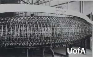 Rosendahl continued, “Another step in the post-MACON research program involved use of an 18-ft. structural model of the ship. This model was slipped into a “cocoon” or cage of surrounding concentric steel rings and held by these rings through a number of calibrated steel springs. These springs could be put in tension or compression to simulate loads that would be experienced by the ship. Numerous tiny mirrors, looking like a flock of butterflies, reflected the slightest movement in the structure of the model, thus providing precision measurements of stresses in girders and wires, and also deformations, under chosen variable load conditions.”
 When these two photos were to be released by Goodyear, the caption was to explain, “The steel rings furnish the bases from which loads are applied to the model. The model was subjected to numerous static and aerodynamic loading conditions. Extensive readings of stresses in girders and wires and of deformations were also made. “

 This model and its resulting diagram of stress analysis on a tail fin structure clearly shows a return to the cruciform reinforcement long favored in Zeppelin design and missing from the ZRS deep-ring concept. In the “Macon post-mortem” report Navy veterans had suggested a return to the wire-reinforced bulkhead design proven in practice.
 Rosendahl continued, “Next, a detailed structural model of a gas cell bay or compartment, 10 feet in diameter, was constructed. It could be used for tests with or without a gas cell installed. Individual wire tensions and stresses of other structural details could thus be measured under inflation or non-inflation.”
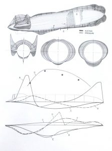
 Obviously the testing generated reports rich with data designers wished they’d had back in 1926-7 when designing the original ZRS ships. Privately funded, the data remained company property. This page shows a mature G-Z design analysis to include cross wind shears, gusts and severe maneuvering. Note the longer, slimmer fins, and exterior, staggered power cars.
A number of the new girders and evolved longerons were created to construct a test section of a ZRCV-like design. This test section was attached to the interior of the Akron Airdock building structure where it was found decades later by Lighter-Than-Air Society volunteers prior to the building’s cleanup and redressing in support of the High-Altitude Airship effort. This photo showing the section was run in the Sept-Oct 2000 issue of BUOYANT FLIGHT, newsletter of the LTA Society. It was again spotted in the fall of 2019 when LTAS trustees were given an Airdock tour.
When the order for a new rigid came, as Goodyear-Zeppelin had every reason to believe it would, the company would have already built-in lessons learned, and were ready to apply the new technology.
 The testing also included where rigids had been, as in this illustration with a generic profile of derived from an amalgam created by imposing the various fineness ratios together after adjusting their sizes for a common scale. Popular Science concluded, “As American scientists continue their researches and as the flying cigars of the Germans once more [are] returned to the transatlantic run, the world is watching to see what will happen. On the side of the Zeppelin, there are many attractions. The rigid dirigible can lift immense loads; is able to float in the air while engines or controls are being repaired. In these respects, it has the advantage over the airplane… Only the future can give us a concluding chapters of the story of Count Zeppelin’s dream.”
Indeed, with the state of the art advanced with both real world experience, realistic testing and theory from the best aeronautical minds in the country, the taxpayer had gotten a huge bang for rather modest bucks. Surely at that time, with WWII looming, all this effort, treasure and lives invested would pay the nation back with the creation of the ZRCV.
Read on to ZRCV: The Giant That Almost Was
or
Read on to LZ-130: The German Rebirth
or
Read on to Durand Committee Reports
or
Read on to The Flying Carrier: The Goodyear Aircraft Proposals
Read on to ZRN: The Rigid’s Last Best Hope
Purchase SNAFU: The Strange Story of the American Airship
Back to Home Page