 The British, in the mid-1920s undertaking two 5 Mil cu ft rigids, had shown how 9 M cu ft capacity would be need for similar performance with helium. With ZR-1 replacements Congress-funded in a 1926 act, but limited by Lakehurst’s 804′ X 172′ hangar, the new design was increased only to 6 Mil cu ft. in hopes of avoiding comparative performance embarrassment. Earliest concepts included lessons learned from the ZR-1 breakup: internal engine rooms, and integrated control car. Also not planned was any way to recover tonnage lost to fuel consumption. As Garlon Fulton later detailed, the ZRS water recovery equipment itself weighed 16,000 pounds. Typical New Jersey weather required an additional 12,000 pounds of anti-freeze. (At 2300 pounds each, that added up to a dozen Waco UBF two-seat hook-on airplanes.) Forgetting its dead weight, on a 6-day mission, the water recovery’s additional drag would increase fuel consumption by 9,000 lbs. It was out of the question.
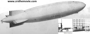
This early concept Goodyear-Zeppelin released to conceptualize the BuAer Design #60 proposal bristles with big guns, with little use for puny auxiliary aeroplanes – nor had funding been provided for them. At some time, possibly in early 1927, a seaplane-carrying truss was added uniquely inside, with details not yet defined. It was about this time that concepts sprouted water-recovery condensers, the necessary evil of their weight and drag making helium operations at least possible if not cost-effective.
 The final 3-keel G-Z design that won the 1928 Zeppelin Rigid Scout competition had been further increased, to 6.5 M cu ft, and featured built-up main rings offering previously unobtainable interior access (left). Amid the other innovative design features learned from non-Zeppelin designs were drivetrains allowing the reversible, inboard German-made engines to drive the propellers through a 90 degree arc, offering thrust in any direction. Chief designer Karl Arnstien also accepted a subordinate’s idea to align all engine rooms along the two side keels to simplify access. G/Y’s huge “Airdock” assembly hangar was more than 50% complete as ZRS-4 assembly began; her “Golden Rivet” was squeezed by RADM Moffett himself during a 7 NOV 29 ceremony.
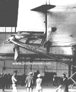 Meanwhile, during the Graf Zeppelin’s 1929 routine replenishment in Los Angeles, his fuel and provison’s weight was balanced with corresponding hydrogen lift piped aboard. Topped off too early, the day’s California sun expanded the hydrogen in the cells, which then vented gas normally through safety valves. That afternoon, the ship could not lift off the mast and no more hydrogen was readily available on site. After sending some crew on ahead by train, and then attempting a heavy, dynamic takeoff on the Graf’s landing bumpers, the lower fin and rudder dug in as the elevator man skillfully wheeled the nose, then the tail, over the Mines Field power lines to safety. (Here, Graf’s rudder under repair after reaching Lakehurst.)
 It is rumored that at the time a comment by Hugo Eckener led on-board observer (future ZRS-4 skipper) C. E. Rosendahl to believe it was necessary to be able to see the lower vertical fin from the control car. True story or not, Navy officers pushed for Design change #2 of 1930. To comply, since hull construction was long since well underway, Arnstien’s design team moved the control car aft, and dramatically altered the fin shape. Author Jeffery Cook’s study on the ZRS fin design discounts the popular story that denying the fin root the strength of main ring 35 was the fatal flaw.

Elsewhere, with no funding to develop a suitable hook-on seaplane, officers accepted they’d have to take an existing plane that would fit through the ZRS-4’s projected door width: 25 feet. No seaplane was right; under consideration were three landplanes, including the Curtiss XF9C-1 (left), a previous competitor for the small-flattop fighter, rejected as too hot to handle. Curtiss corrected many of the problems using its own money, building an improved XF9C-2. Equipped with a sky-hook and successfully tested on ZR-3’s trapeze, an order was placed for six production units. One advantage was noted over the USS Langley then testing landplanes in its added flat-top deck: the airplanes could launch and recover without the parent vessel having to turn into and hold a steady course to keep the prevailing winds straight down its deck. Few appreciated at the time what would later be demonstrated in ZRS ops: airplanes could hook on or drop off with their dirigible on any heading, with any relative wind. (In fact as told by pilot “Min” Miller, pilots adapted to the airship’s actually changing course while they were in approach for hooking on.)
 Visitors to the Airdock viewing ZRS-4 construction were treated to explanatory signs labeling some components in Bay VII, location of the airplane stowage truss structure. The airplane trapeze was not part of the contract; neither it, nor the default airplanes, could be pre-tested before rollout.
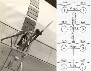 First-ever inline engines, numbered per the diagram at left, had to turn in opposite directions for best prop efficiency. Various pitches – even steel props in ZRS-4’s later days – were tried. Accepting the peacetime helium edict, each engine was plumbed with complex exhaust-cooling condensers with associated piping and baggage to recover water tonnage created in the combustion process. The arduous task of cleaning the sooty plumbing would be come to be handed out as punishment to enlisted crewmen for violating minor rules.

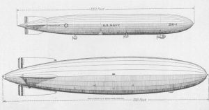
This NAS Lakehurst Engineering handling drawing (right) shows the ZRS-4 &5’s main frame and bay/cell Roman Numeral designations; our inset contrasts the original fin plan. With a final length of 785 feet and maximum diameter of 132.9 feet. the overall ZRS 4&5 hull air enclosure was 7,401,260 cu ft allowing 12 gas cells a maximum displacement of 6,850,000 cu ft. 126,000 lbs. of gasoline weight contained in 110 keel tanks, and the additional weights of oil tanks, water tanks, and ballast bags were spread along the twin outboard keels, which also served as main ship’s passageways from frame 35 aft to frame 170 forward.
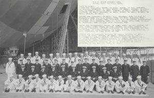 Here, the “plankowners” pose in the Airdock with their ship on 30 JUL 31, about six weeks before rollout. It would be up to these men and their future shipmates to learn the art of operating the first rigid designed to accommodate the limitations of helium. With these and so many other major design innovations in the ZRS-4 evolution, there was a great deal for them to learn before airplanes could be incorporated into operations.
 In a ceremony attended by thousands, ZRS-4 was christened by Mrs. Herbert Hoover, sent by her husband the President in a show of support. She pulled a rope signaling the forward yaw line hatches to pop open, releasing 48 doves “of peace” that had been staged inside. The lines were let out so the 200-ton airship could float up several feet, while the crowd cheered.
Columbia Pictures had jumped on the chance to release its new film “Dirigible” starring Jack Holt, Ralph Graves and Fay Wray, playing in local theaters that week.
Click > for a clip from our DVD, “The Flying Carriers” ( sound on)
Read on to USS Akron Arrives
or
Back to Design for Helium
or
Back to American Zeppelins